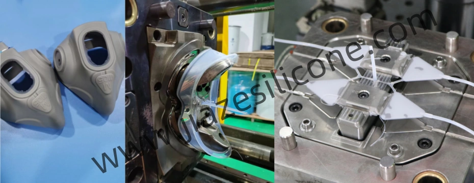
Liquid Silicone Rubber (LSR) molding is a popular manufacturing process for producing flexible, durable, and high-precision parts. Despite its many advantages, this process can encounter defects that compromise the quality of the molded components. Understanding this common definition in lsr molding, its causes, and potential solutions is crucial for ensuring high-quality production.

1. Flash
Definition: Flash refers to excess material that escapes from the mold cavity and forms thin layers around the edges of the molded part.
Causes:
- Poor clamping pressure or insufficient mold closing force.
- Damaged or worn-out mold seals and parting lines.
- Incorrect tooling design with loose tolerances.
- Over-pressurization of the injection system.
Solutions:
- Ensure precise mold design and maintenance to eliminate gaps in the parting lines.
- Optimize clamping force and injection pressure settings.
- Regularly inspect and replace worn mold components.
2. Short Shots
Definition: Short shots occur when the mold cavity is not completely filled, resulting in incomplete parts.
Causes:
- Insufficient material injection or low shot volume.
- Blockages or restrictions in the runner system.
- Inadequate venting, causes air to trap in the cavity.
- Low injection pressure or speed.
Solutions:
- Increase shot volume or adjust injection pressure and speed.
- Optimize runner and gate design to ensure smooth material flow.
- Improve mold venting to eliminate trapped air.
3. Sink Marks
Definition: Sink marks are surface depressions caused by uneven cooling or shrinkage during the curing process.
Causes:
- Uneven wall thickness in the part design.
- Insufficient packing pressure or holding time.
- Overly high mold or material temperature.
Solutions:
- Design parts with uniform wall thickness to minimize shrinkage.
- Adjust packing pressure and hold time to allow proper material distribution.
- Optimize temperature settings for uniform curing.
4. Burn Marks
Definition: Burn marks appear as discolored areas, usually black or brown, caused by material degradation or trapped air overheating.
Causes:
- Excessive injection speed or pressure.
- Poor mold venting leads to trapped air compression.
- High material temperatures cause thermal degradation.
Solutions:
- Reduce injection speed and pressure to prevent overheating.
- Enhance mold venting to allow trapped air to escape.
- Maintain proper material temperatures during molding.
5. Air Bubbles or Voids
Definition: Air bubbles or voids are internal or surface defects caused by trapped air or gas.
Causes:
- Poor venting of the mold cavity.
- Fast injection speed trapping air during filling.
- Insufficient de-gassing of the LSR material.
Solutions:
- Ensure adequate mold venting and use vacuum-assisted molding if necessary.
- Reduce injection speed to minimize air entrapment.
- Thoroughly mix and de-gas the LSR material before molding.
6. Flash Back
Definition: Flash back is a defect where the material flows back into areas beyond the cavity, often contaminating other mold components.
Causes:
- Overfilled cavities due to excessive shot volume.
- Improper clamping pressure or worn seals.
- Excessively high injection pressure.
Solutions:
- Fine-tune the shot volume and injection pressure.
- Maintain mold components, including seals and parting surfaces.
- Use proper clamping force to secure the mold tightly.
7. Flow Lines
Definition: Flow lines are visible lines or streaks on the surface of the part, caused by material flow inconsistencies.
Causes:
- Low mold or material temperature, causing uneven material flow.
- Poor gate or runner design leads to turbulence.
- Improper injection speed.
Solutions:
- Increase mold and material temperatures for smoother flow.
- Optimize gate and runner design for consistent material entry.
- Adjust injection speed to eliminate turbulence.
8. Tearing
Definition: Tearing occurs when the part is damaged during ejection or demolding.
Causes:
- Insufficient curing time leads to weak parts.
- Aggressive ejection forces.
- Complex part geometry with sharp undercuts or inadequate draft angles.
Solutions:
- Allow adequate curing time to ensure complete crosslinking.
- Use appropriate ejection systems with softer forces.
- Redesign parts to include draft angles and avoid sharp undercuts.
9. Warpage
Definition: Warpage is a distortion of the molded part, leading to irregular shapes.
Causes:
- Uneven curing due to temperature imbalances in the mold.
- Non-uniform material distribution or inconsistent wall thickness.
- Premature ejection of the part before complete curing.
Solutions:
- Maintain consistent mold temperatures.
- Design parts with balanced wall thickness.
- Allow adequate curing time before ejection.
10. Overcuring
Definition: Overcuring causes brittleness or discoloration in the molded part due to excessive curing time or high temperatures.
Causes:
- Excessively high mold temperatures.
- Prolonged curing times beyond the recommended duration.
Solutions:
- Follow the manufacturer-recommended temperature and curing parameters.
- Regularly calibrate mold temperature controls.
11. Inconsistent Surface Finish
Definition: Surface irregularities such as roughness, matte finishes, or gloss differences across the part.
Causes:
- Poor mold surface finish.
- Inconsistent material properties or contamination.
- Inadequate or fluctuating mold temperatures.
Solutions:
- Ensure molds are polished to the desired finish level.
- Use high-quality, uncontaminated LSR material.
- Maintain stable mold temperature throughout the cycle.
12. Sticky Parts
Definition: Sticky parts occur when the molded components adhere to the mold, making ejection difficult.
Causes:
- Insufficient mold release agent or excessive mold roughness.
- Under-curing of the material.
- Inadequate draft angles in the mold design.
Solutions:
- Apply mold-release agents as needed but sparingly to avoid contamination.
- Ensure complete curing of the material before ejection.
- Incorporate appropriate draft angles to facilitate part removal.
Conclusion
Defects in LSR molding can stem from a variety of sources, including tooling, material handling, process settings, and part design. By identifying the root causes and implementing targeted solutions, manufacturers can significantly reduce these defects, ensuring consistent quality and efficiency in production. Proper mold maintenance, optimized process parameters, and precise part designs are essential for minimizing defects and achieving high-quality LSR products.